MIL-PRF-83178C
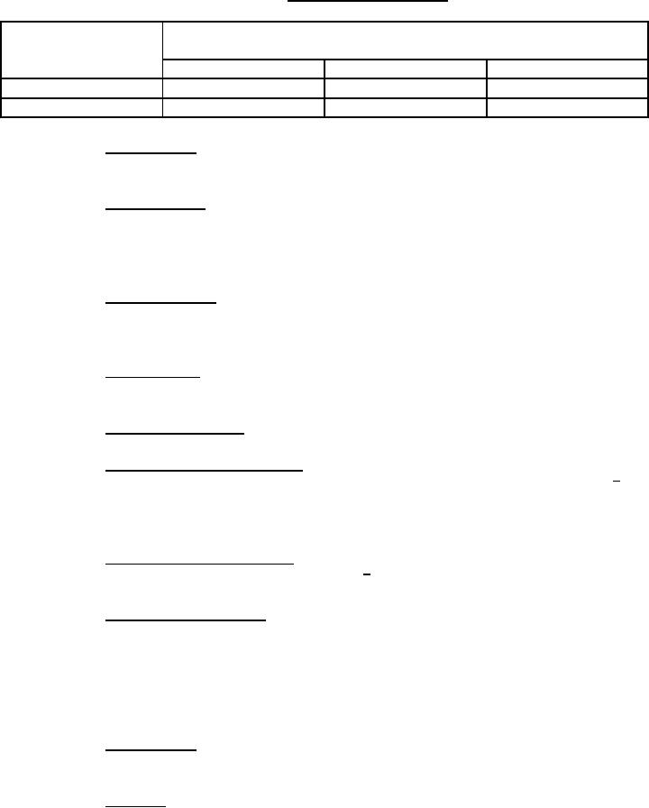
TABLE IV. Pressure range tolerance
Pressure variation tolerances for flow rate changes from
Outlet pressure range
(inches of water)
(inches of water)
10 to 0 LPM
10 to 70 LPM
10 to 135 LPM
1.0 to 2.0
1.0
-0.9
N/A
2.0 to 15.3
1.3
N/A
-1.3
3.6.13 Static leakage. The regulator static pressure leakage shall be less than 0.01 LPM
during a 2 minute period.
3.6.14 Inward leakage. With the diluter lever in the normal oxygen position, the supply
lever in the off position, and a suction of 10 inches of water applied at the outlet, the inward
leakage through the regulator at a pressure altitude of zero feet shall be less than 0.2 LPM (see
6.8).
3.6.15 Outward leakage. With a pressure of 17 inches of water applied at the outlet of
the regulator, outward leakage through the regulator, including the pressure relief device, shall be
less than 0.12 LPM.
3.6.16 Outlet leakage. With the supply lever in the on position, the leakage at the outlet
of the regulator shall be less than 0.01 LPM.
3.6.17 Supply valve leakage. The supply valve leakage shall be less than 0.001 LPM.
3.6.18 Emergency pressure operation. With the pressure lever in the emergency
position and the diluter lever in the normal position, the regulator outlet pressure shall be 3.5 +0.5
inches of water at a flow of 10 LPM. At a flow of 80 LPM, the outlet pressure shall be greater
than 2 inches of water.
3.6.19 Test mask position operation. With the pressure lever in the test mask position,
the regulator shall provide 10 LPM at a pressure of 11 +5 inches of water at the outlet.
3.6.20 Flow indicator operation. With diluter lever in the 100% oxygen position, the
indicator shall provide full flow indication for an outlet flow of 4 LPM at a pressure altitude of
zero feet, and an outlet flow of 8 LPM at a pressure altitude of 35,000 feet. With the diluter lever
in the normal oxygen position, a full flow indication shall be provided for a flow of 18 LPM at
all pressure altitudes. With the flow reduced to 0 LPM, at all pressure altitudes, and the diluter
lever in either position, the flow indicator shall show no indication of flow.
3.6.21 Panel lighting. The regulator panel shall be provided with lighting conforming to
the table on figure 1 and SAE-AS7788. The panel shall not cause electromagnetic interference.
3.6.22 Overload. With supply lever in the off position and the diluter lever in the 100%
oxygen position, the regulator shall withstand a pressure of 27 inches of water applied at the
outlet for a period of 2 minutes.
9
For Parts Inquires submit RFQ to Parts Hangar, Inc.
© Copyright 2015 Integrated Publishing, Inc.
A Service Disabled Veteran Owned Small Business