MIL-PRF-83867D (USAF)
appropriate density correction factors shall be applied to the flowmeter and to the performance
of the connector.
4.5 Requirements cross-reference matrix.
Table II provides a cross-reference matrix of the section 3 requirements tested or verified in
section 4.
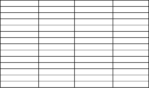
TABLE II. Requirements cross-reference matrix.
Requirement
Verification
Requirement
Verification
3.1
4.2
3.6.3
4.6.1
3.3
4.6.1
3.7.1
4.6.2
3.3.1
4.6.1
3.7.2
4.6.3
3.3.2
4.6.1
3.7.3
4.6.4
3.3.3
4.6.1
3.7.4
4.6.5
3.3.4
4.6.1
3.7.5
4.6.6
3.4
4.6.1
3.7.6
4.6.7
3.5.1
4.6.1
3.7.7
4.6.8
3.5.2
4.6.1
3.7.8
4.6.10
3.5.3
4.6.1
3.7.9
4.6.9
3.6
4.6.7, 4.6.8
3.8
4.6.1
3.6.1
4.6.1
3.9
4.6.1
3.6.2
4.6.1
4.6
Tests.
4.6.1 Examination of product.
Each connector shall be examined to determine conformance with this specification with respect
to materials, design, interface, lubrication, markings, interchangeability, and tightness or locking
of threaded parts. There shall be no evidence of cuts, nicks, or holes in the connector hose.
4.6.2 Disconnection force.
A jig that has the internal dimensions of the connector specified in MS22058 shall be used for
this test. The connector shall be inserted and disconnected from the aircraft supply port by
applying sufficient load along the longitudinal axis of port. The load shall be measured to
determine conformance with the load requirements of 3.7.1. This test shall be performed three
times on each connector.
4.6.3 Disconnection force reliability.
The jig specified in 4.6.2 shall be used for this test. The connector shall be inserted and
disconnected from the aircraft supply port at a rate of 20 cycles per 24-hour period for a total of
25 periods. The disconnection force for each cycle during the test shall meet the requirements
of 3.7.1. The disconnection force for the three initial and three final cycles of each 20 cycle run
shall be averaged and reported.
9
For Parts Inquires submit RFQ to Parts Hangar, Inc.
© Copyright 2015 Integrated Publishing, Inc.
A Service Disabled Veteran Owned Small Business