MIL-DTL-87255A(USAF)
3.4.2 Relief valve.
The valve shall include a pressure relief valve that shall not allow the valve outlet pressure to
the anti-g suit and the sense line (if applicable) to exceed 13 psig.
3.4.3 Lubrication.
The valve shall be designed and constructed in such a manner that no maintenance lubrication
shall be required.
3.4.4 Inlet screen.
The valve shall contain a corrosion-resistant steel, 30 by 30 maximum mesh, 0.010 inch
minimum wire diameter inlet screen. All inlet air shall pass through the screen.
3.5
Performance.
All specified performance requirements shall be based on the use of air.
3.5.1 Minimum operating acceleration force.
The minimum equivalent acceleration force required to open the valve to permit flow of 0.01 liter
3.5.2 Outlet pressure regulation.
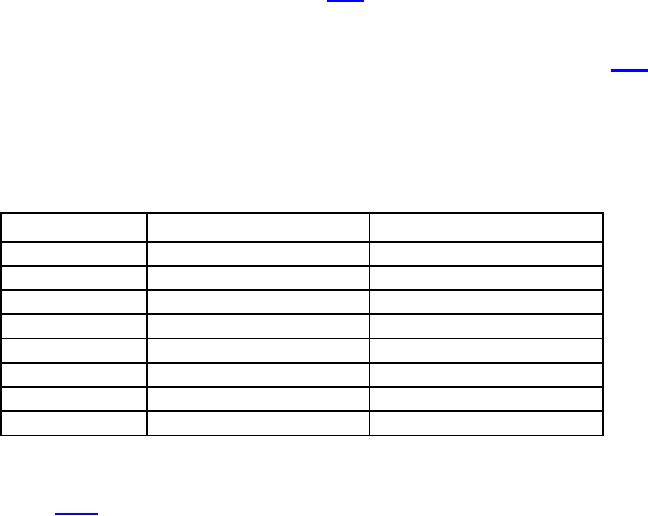
For a constant applied acceleration force, the outlet pressure schedule during testing (see 4.5.3)
shall be within the range specified in table I and displayed graphically on figure 4 for both
gradual onset/offset (<= 0.1 Gz/sec) and rapid onset/offset (= 4.0 Gz/sec). Outlet pressure shall
be met within 2.0 seconds of reaching the constant force when accelerating and within 5.0
seconds of reaching the constant force when decelerating. The outlet pressure shall not
fluctuate more than ±0.1 psi at any given constant acceleration force.
TABLE I. Outlet pressure.
G-Range (Gz)
Maximum Pressure (psig)
Minimum Pressure (psig)
0 1.80
-
0
1.80 2.00
Gz 1.80
-
2.00 4.00
1.40 +Gz 2.60
-
4.00 9.33
1.50 +Gz 3.00
-
> 9.33
-
11.00
1.25 4.00
1.45 +Gz 1.80
-
4.00 10.00
1.50 +Gz 2.00
-
>10.00
13.00
-
3.5.3 Leakage.
The leakage to the ambient shall not exceed 1.0 liters per minute. There shall be no leakage to
the outlet (see 4.5.4).
5
For Parts Inquires submit RFQ to Parts Hangar, Inc.
© Copyright 2015 Integrated Publishing, Inc.
A Service Disabled Veteran Owned Small Business